The Filling Tube System
Loading of the flammable liquids into railcars using the filling tube system is based on the on-spot principle. The products can be fed to the filling tube system via various product lines and the associated product collectors. Loading can be carried out on each track using a filling tube system.
Additional filling tube systems can be retrofitted on any track.
The filling tube system consists of:
- Filling tube sledge
- Filling tube
- Swivel joints
- Hydraulic unit
- Pneumatic unit
- Optional: Ground monitoring
The filling tubes of a track are mounted next to each other in the filling tube sledge along the track axis. The filling tube sledge is mounted on rollers and enables the filling tubes to move transversely (+/- 100 mm) and longitudinally (approx. up to 10 m) via the hydraulic system. The transverse movement is driven by one or two hydraulic cylinders that are operated in parallel. The longitudinal movement is driven by a hydraulic motor.
The movement commands for transverse and longitudinal movement can be given by operating the joystick in the control panel in the control room. The operating personnel can see the filling point through the windows of the operating room and can use the transverse and longitudinal movement to position the filling pipe selected for loading exactly over the dome opening. The end positions of the longitudinal and transverse movement and the center position of the transverse movement are detected by sensors.
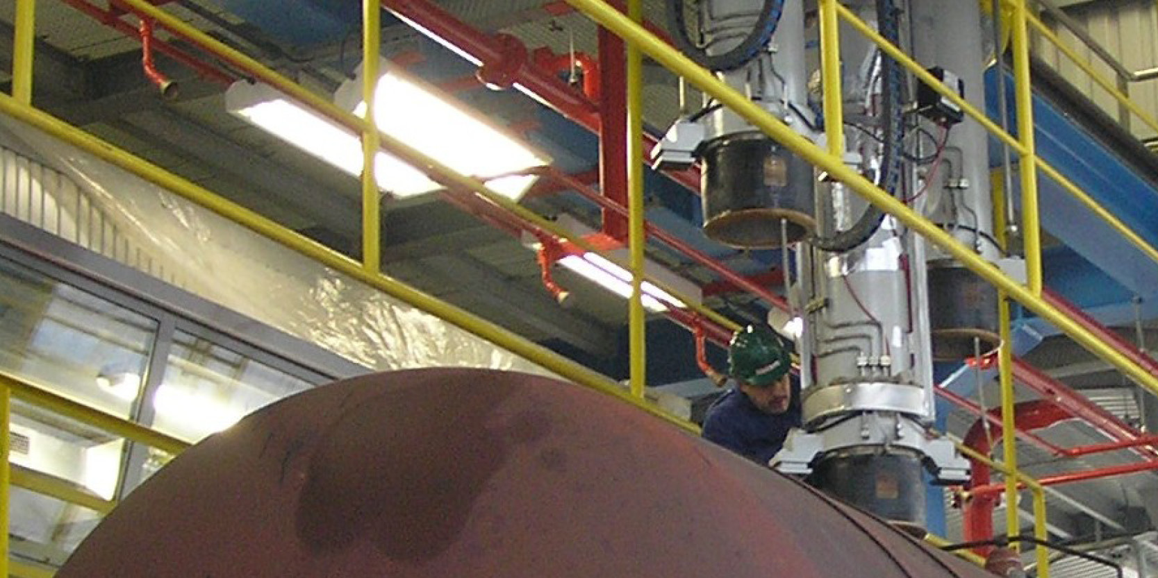
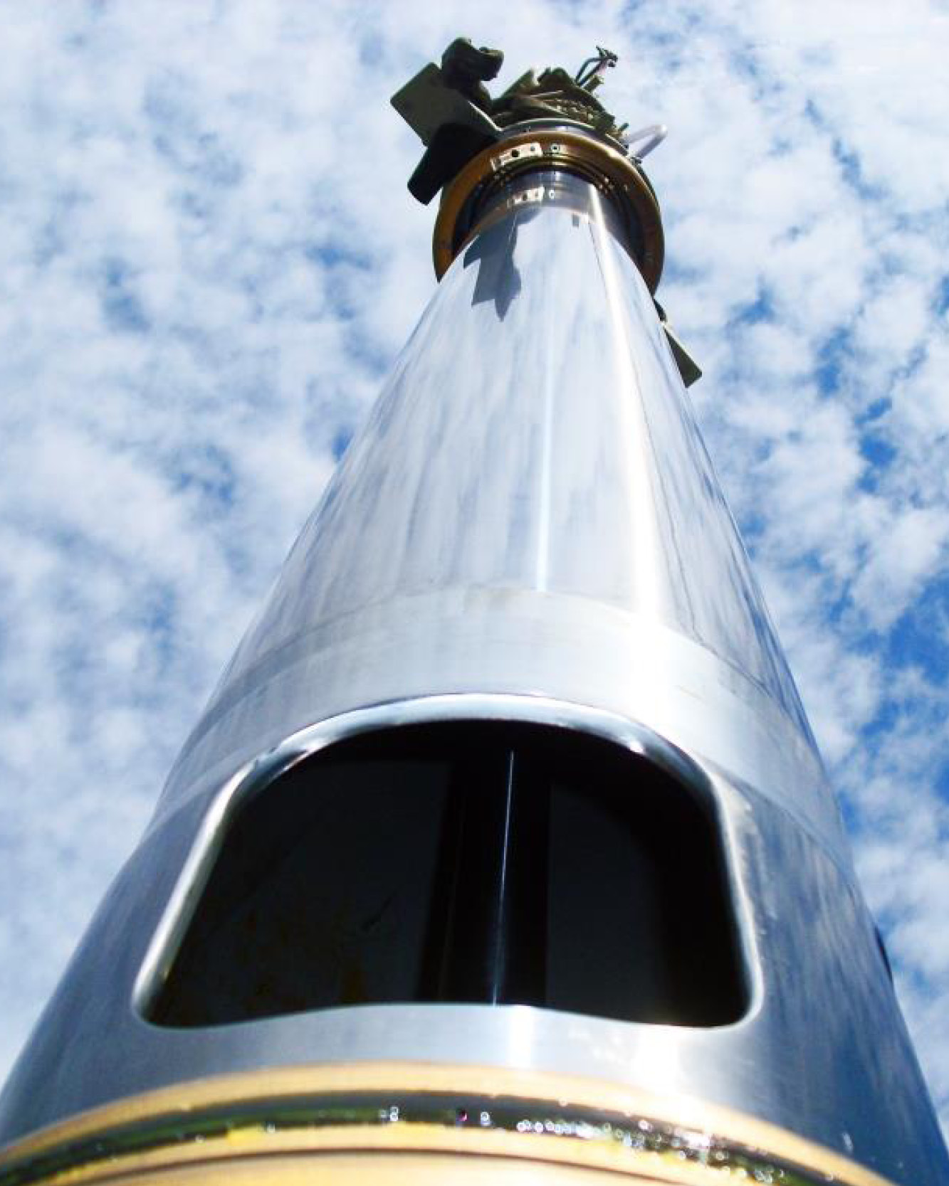
The filling tubes are machine-made in a high-quality design. The weight of a filling tube is between 1,600 and 2,000 kg, depending on the design. The guide surfaces are hard chrome-plated and bronze-guided. The wall thicknesses of 10-20 mm, depending on the filling tube component, are designed for a very long service life. With regular maintenance, service lives of up to 35 years are possible.
To move in and out of the railcar, the filling tubes are equipped with an internal hydraulic cylinder with which the filling tube reaches an extension length of 4,250 mm (Western Europe), 4,700 mm (Eastern Europe) or in accordance with the country-specific tank car types. The end positions “filling tube up” and “filling tube retracted into tank car” are monitored with initiators.
In the upper end position, the filling tube has a mechanical lock.
The product is fed through the 200 to 300 mm inner diameter of the filling tube (standard filling tube 230 mm) and the product connection piece of the articulated swivel joints or telescopic tubes. The gas is returned through the filling tube and the vertical gas telescopic pipe via the product connection piece of the gas swivel joints or the gas telescopic pipe. The inflatable sealing bellows or sealing plate (Eastern European tank cars) attached to the filling tube allows the tank car to be hermetically sealed during loading. The filling tubes are equipped with overfill protection based on the bubble principle or with a special mechanical overfill protection probe and pressure monitoring.
All parts touching the railcar are made of bronze. The grounding of the railcars is achieved via grounding contacts on the filling tube when the filling tube is placed and monitored by a grounding test device (automatic grounding). If the railcar cannot be grounded by the automatic grounding, grounding can be established using the second grounding test device. Grounding monitoring for railcars is required on a country-specific basis. In Germany, for example, separate earthing monitoring for railcars is not necessary.
Further monitoring is carried out in the associated pneumatic cabinet and hydraulic cabinet.
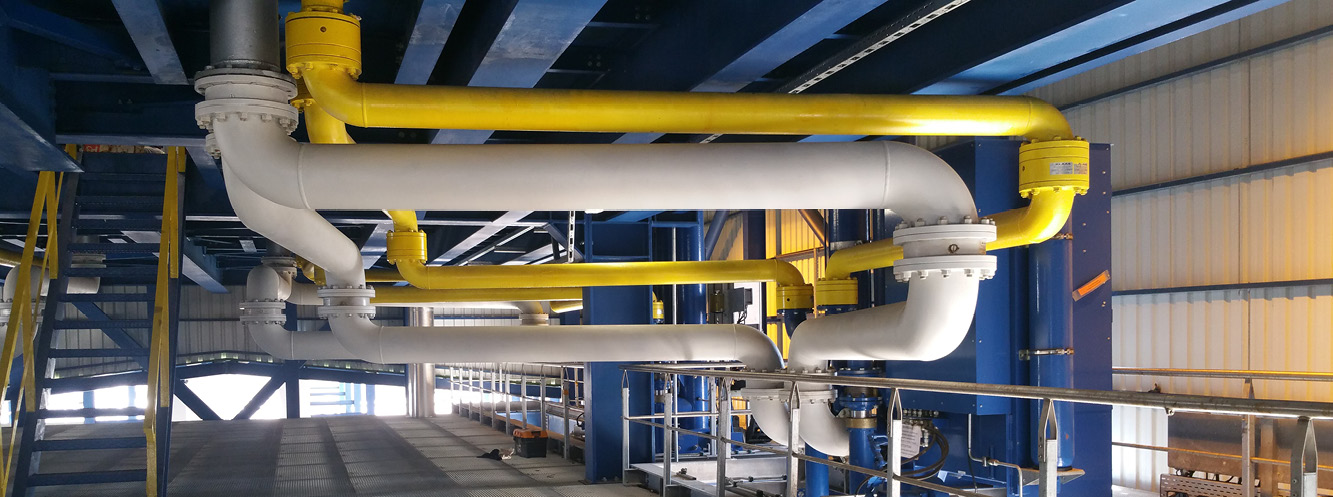
The decision as to which system is used to connect the filling tube technology to the system side depends on the required movement range of the filling tubes. This movement range depends on the dimensions of different railcars to be loaded.
The gas return of the filling tube is connected to the gas return line via a gas swivel joint or gas telescopic tubes. The gas return is usually equipped with pneumatically controlled fittings with which the gas line can be shut off. Continuous pressure monitoring of the gas phase in the railcar and the gas line protects the steam system from impermissible over- or under-pressure.
The filling tubes are connected to the various product distributors via articulated swivel joints or telescopic pipes. The articulated swivel joints/telescopic pipes for product lines and gas lines enable the filling tube to move in the horizontal plane (left, right, forward and backward).
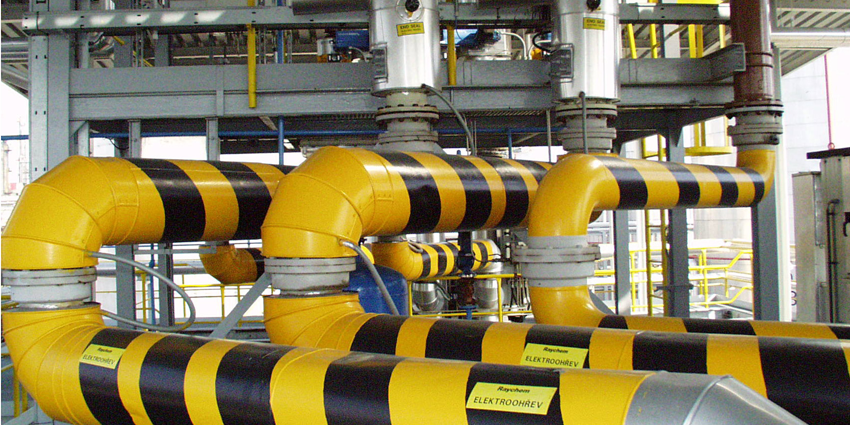
A hydraulic system is usually installed for each filling tube system. The hydraulic system (designed according to ATEX guidelines or country-specific Ex requirements) controls the filling tube mechanics. The hydraulic pressure required for the required hydraulic movement is provided by a hydraulic pump motor combination.
The hydraulic motor is only activated when hydraulic pressure is requested by appropriate functions. The following functions are provided:
- Selection Filling tube
- Filling tube upwards or downwards
- Filling tube sledge left or right
- Filling tube sledge forward or backward
- Filling tube over Hydraulic accumulator upwards
- Wastegate
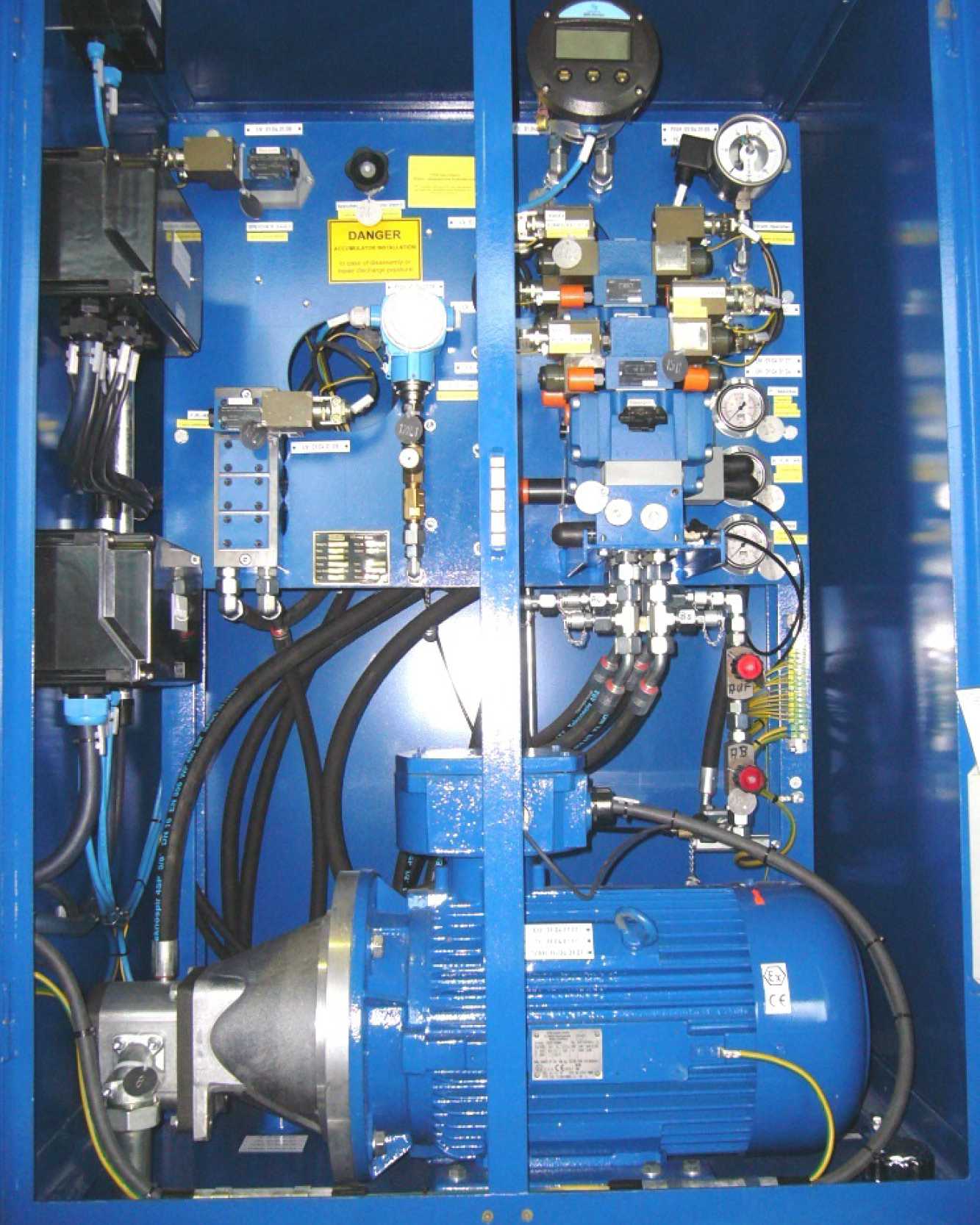
A pneumatic system is installed for each filling tube system on a track. The pneumatic system controls and monitors the sealing bellows (Western European tank wagons), the overflow protection (alternatively: probe system) and the overpressure monitoring of the railcar during loading. All air lines are routed via the vertical drag chain of the filling tube to the air connections of the outer pipe.
The pneumatic cabinet is usually equipped with insulation and an electric heater and is mounted on the filling tube trolley. The necessary connecting cables and hoses (electrical and pneumatic) are routed via a drag chain.
General, activation of filling tube
The instrument air is cleaned by the filter and the condensate is separated by an automatic drain. Depending on the selected filling tube, the assigned 3/2-way solenoid valve for activating the overflow protection, overpressure monitoring and sealing cushion is activated on the selected filling tube.
A filter regulator is connected upstream of the 3/2-way solenoid valve for filling the sealing cushion. A precision pressure regulator is installed in front of the 2/2-way valve of the overfill protection.
Overfill protection
When a filling tube is activated, the pressure lines of the overflow protection and pressure equalization line are switched to the corresponding filling tube. The air lines of the overflow protection and the pressure measurement are thereby connected to the overflow protection hose and the pressure measurement line of the activated filling tube.
When the filling tube system is put into operation, the overflow protection is set so that the overflow protection is switched off at the maximum permitted filling level.
As an alternative to the pneumatic overfill protection, we also offer special probes for switching off limit values. Please request separate information via email.
Pressure measurement gas phase
When a filling tube is activated, the pressure equalization line is switched to the corresponding filling tube. The air line of the pressure transmitter is thereby connected to the pressure measuring line of the activated filling tube.
This allows the pressure in the railcar to be monitored. If the pressure in the gas pipe increases to up to 300 mbar (country specific), the filling process is automatically switched off.
Advantages of SCHERZER filling tube technology
Our robust filling tubes are manufactured using high-quality machine technology and weigh approx. 1,600-1,850 kg. Many of the filling tubes we supply have been in successful use for over 30 years. The pipes have wall thicknesses of 10-20 mm, ground and hard chrome-plated guide surfaces and parts made of brass or red brass, including an NBR sealing plate (Eastern European tank wagon). For Eastern European railcars, the sealing plate is spring-mounted and protected with sturdy brass strips. The overfill protection, overpressure protection and continuous loading status display ensure high operational safety.
The gas return takes place through a separate, high-quality telescopic tube with multiple seals to avoid condensation formation. A flexible compensator allows the protective tube and the inner tube to be deflected without the filling tube having to be centered (except for Eastern European tank cars). During the entire loading process, the claws lie firmly on the dome, which means that no rubbing movements occur on the sealing bellows and the service life of the bellows is long.
The hydraulically remote-controlled longitudinal and transverse movement enables precise positioning. The sealing after removal from the railcar is done by two O-rings, whereby residual quantities drip off the pipe walls and are emptied into the railcar the next time it is loaded (max. approx. 10-15 liters).
Over the last 40 years, we have assembled and commissioned more than 350 filling pipes in different countries. Our constant development results in a filling system that represents the current state of the art and has proven itself under extreme conditions in decades of continuous operation.
The PLC-controlled loading process meets all safety requirements. If desired, each filling tube position can be displayed visually and the filling tube stroke can be limited depending on the railcar type.
You can find a clear summary in our brochures under downloads.
Find out more about our individual areas of rail car handling systems here
On-Spot-Loading-Facilities Single- and Serial loading Bottom loading Unloading

